


National Trench Safety recently previewed its newly developed telemetric pin at the CONEXPO/CON-AGG construction equipment show in Las Vegas, Nevada. The telemetric pin was installed within the leg of a hydraulic excavation brace supporting an 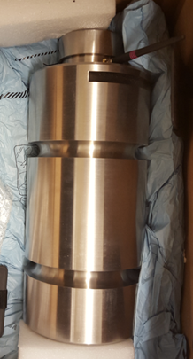 in-ground slide rail pit. As part of the demonstration, hydraulic loads were applied to the pin which was wirelessly transmitted to a processing website that could output the data to a computer or mobile phone, as well as send text message alerts. The telemetric pin generated a lot of interest and questions that I will try to expand upon within this article.
Innovation within the Shoring Industry
Load measuring pins have been used for many years in bridges and strutting applications for the purpose of measuring loads within a structural element that is designed to resist forces along the axis of the member, a column is an example of this. In shoring applications, the soil loading applies a force perpendicular to a member and the member is most likely to fail by bending. Shoring walls and wale beams are examples of this. The NTS Telemetric Pin is a new application within the shoring 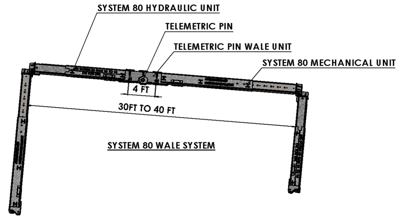 industry because, for the first time, the pin enables measurement of bending forces, the forces most likely to cause a shoring failure. The pin is also designed to enable the accurate prediction of shoring wall deflection. Shoring wall deflection is the result of ground movement that leads to settlement. The NTS load-measuring telemetric pin enables continuous monitoring of bending forces and wall deflection. This innovation offers early detection of excessive forces so the problem can be fixed before a failure occurs.
Simply stated, the telemetric pin load measuring system reacts to soil loading, and transmits the loads measured to a website that shows them on a graph as well as other pertinent information that can be derived from the information. Alarms points can be established that will trigger a cell phone notification if design parameters are about to be exceeded. Real-time continuous load monitoring and notification are new to the excavation shoring industry.
The initial rollout of the telemetric pin system focuses on NTS’s series of hydraulic excavation brace systems for larger excavations. The system would feature the installation of the telemetric pin in the wale and hydraulic sensors within hydraulic units. NTS is currently adapting the telemetric pin for use within other protective systems, including shoring shields, hydraulic shores, slide rail systems, sheet piling systems, and more.
Telemetric Pin Usage – When and How
There are many different reasons to use the load-measuring telemetric pin in a shoring application depending on the user. Primary use decision makers are:
Project owner and design engineer
The project owner’s design engineer is charged with ensuring that all mandated shoring requirements are implemented on the project. To fulfill this requirement the design engineer reviews shoring design submittals for several issues, including the design engineer’s assumption of soil and surcharge loading. Until now the design engineer never has had the ability to confirm the accuracy of those assumptions and monitor those throughout the excavation process. Telemetric pin load monitoring is a powerful tool that can be used to confirm the shoring design is not being exceeded. If deflection criteria are part of the contract requirements, the system can verify that the deflection is not exceeded or pinpoint the time and duration it was exceeded. Surveys and deflection checks are always at a point in time only. At the bid stage the project designer can specify “at shoring applications, a continuous load monitoring and reporting system shall be established that is active throughout the time the shoring is in place,”
Contractor
On critical projects where shoring system failure would be catastrophic, the contractor can have the assurance that load assumptions are not being exceeded and have time to do something about it if the loading is approaching critical limits.
In cases of large surcharges, the setback can be adjusted, closer than planned, or 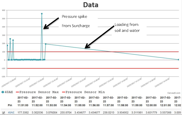 pushed back depending on the soil pressure developed at the time. Soil pressure builds up over time and is most often predicted to be much higher than it really is. Setbacks for crane pics and other large equipment are also set very conservatively. Shoring designers are constantly being asked during the time of construction to relax the setback requirement or the limits are simply being exceeded without permission because no one is looking.
Contractors will be given far more leeway and cost-effectiveness in shoring design if load predictions are confirmable.
Note: this is a general discussion of concepts. Some or all of these adjustments, such as setback adjustment, for example, may require the approval and stamp of a registered professional engineer. It is the Competent Person’s responsibility to evaluate the use of the product and ensure compliance with the 1926 OSHA Subpart P Standard.
Shoring designer
Telemetric load monitoring will allow shoring designers to confirm soil and surcharge loading assumptions. To date, soil load theories are based on mathematics and theory. Many experienced shoring design engineers believe that the current apparent earth pressure theories are extremely conservative in many instances and not safe enough in certain cases. The effects of soil arching, moving loads, time in the ground, staging, speed of excavation, soil type, and stratification are not considered in these theories. Popular surcharge loading theories do not take soil type and duration into consideration. Measured results from actual real-time shoring loading will improve confidence and accuracy of soil load predictions thereby allowing for safer and more cost-effective shoring designs.
The impact on the level of certainty and safety of the workers inside the excavation will be huge.
Improper dewatering and exceeding allowable surcharge load limits are common causes of shoring failure and excessive ground movement. With the continuous load 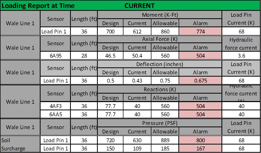 monitoring system these occurrences will be pinpointed and measured exactly as they occur.
Structural design engineers focus on allowable stress in the design process. Axial, Bending, and shear forces as well as deflection determine the safety of the structure. Load monitoring systems allow the measurement of all of these criteria on a continual basis during the life of the shoring system. Shoring designers and engineers on the owner’s side can go to the web site and look at these reports at any time.
Future Electronic Monitoring Applications
National Trench Safety is currently working to adapt and incorporate the technology into other systems, including trench shields, slide rail systems, sheet piling systems, and steel plates. This will complete the technology so that any shoring system can be monitored. The design and usage of these shoring elements are based on anticipated soil loads and soil arching.
For more information on the telemetric pin system, its design and use, or other general questions please contact your nearest NTS branch office.
DISCLAIMER: the information contained in this article is provided for general and illustrative purposes only and is not to be considered Site Specific and or designated engineering for any project or work zone, nor is it to be used or considered to be tabulated data, technical data, advice and or counsel to be used on any job site. Each project is different and is the responsibility of the employer’s designated Competent Person to make decisions on what systems and methods may be used in compliance with the federal and local regulations, manufacturers tabulated data, engineered drawings, and other plans.