In almost all cases, a Competent Person must first classify soil in accordance with the OSHA Appendix A Soil Classification prior to selecting open-cut sloping or a manufacturer shoring system for a project. The appendix outlines three soil types in descending order of stability, Type A, Type B, and Type C. Anyone that works with excavation shoring systems and has had a Competent Person training class should recognize these terms and understand them to some extent. The intent of this article is to provide a good understanding of how these soil types originated and how they are defined and to gain a physical sense of these divisions. Most of us in this industry have read Appendix A and had some instructions on OSHA Soil Types. Here I have tried to present a more intuitive and logical approach to understanding soil types.
Soils can be sorted and classified based on various characteristics such as color, fertility, permeability, strength, weight, chemical composition, organization, and the list goes on. The OSHA Appendix A soil type system is focused on soil strength and stability, specifically in the case of open cutting the soil it looks at what a safe slope angle would be, and in the case of shoring how much horizontal force a vertical column of soil will transmit to a shoring face. This is different than the uniform soil classification system or the agriculture classification systems that sort for many different properties. Appendix A system uses many of the same terms and definitions but is specifically directed to the stability of the soil and is to be determined and applied by construction workers, not engineers and technicians. The short definitions are:
“Type A” means cohesive soils with an unconfined, compressive strength of 1.5 ton per square foot (tsf) (144 kPa) or greater.
“Type B” means:
(i) Cohesive soil with an unconfined compressive strength greater than 0.5 tsf (48 kPa) but less than 1.5 tsf (144 kPa); or
(ii) Granular cohesionless soils including angular gravel (similar to crushed rock), silt, silt loam, sandy loam, and, in some cases, silty clay loam and sandy clay loam.
“Type C” means:
(i) Cohesive soil with an unconfined compressive strength of 0.5 tsf or less; or
(ii) Granular soils including gravel, sand, and loamy sand; or
(iii) Submerged soil or soil from which water is freely seeping;
The three key terms are cohesive soils, non-cohesive soils, and water. They are related as follows:
- The stability of Cohesive soils is based on chemical and electrical bonding
- The stability of non-cohesive soils is based on friction
- Water decreases the stability of both soil types, water:
- weakens the electrical bonds in cohesive soils
- decreases the vertical weight of granular particles and clay particles when submerged thereby decreasing the resisting friction force
Clay particles are flat, microscopic, and have an electrical bond. Depending on how the particles are laid in, close, and aligned (over time they seek this position) or randomly placed and on the water content of the mixture the strength of clay varies.
Non-cohesive soils are solid particles varying from sand to gravel to rocks and shale. Their stability is based on friction which in turn is based on the roughness and angularity of the particles. The more rounded the particles the less stable they are. Angularity and the water level is really the only thing that sets Type B and Type C soil apart. Rounded particles are the result of rock tumbling which is common with water-washed soils in stream beds and on beaches.
Soil is almost always some mixture of clay and non-cohesive particles. If you put a sample in a jar of water and shake it up the rock particles will settle to the bottom and the clay particles will settle on top. Classification is quite simple, if the clay content measures more than 50% it is classified as cohesive, if not then it would be non-cohesive. Another interesting fact about particle distribution is that the smallest size particles in the soil have the largest impact on the strength of the mixture. For example, in a concrete mixture, the cement particles have the largest impact on the strength. In dry conditions, or damp (less than saturated), the larger the amount of clay particles in the soil mixture the stronger it is going to be.
It is also important to note that Type A soil is only defined as cohesive. If the soil is non-cohesive it can only be Type B or Type C. The separator for non-cohesive B degraded to C is the angularity of particles and water content.
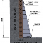
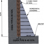
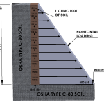
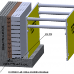
The physical impact or result of the classification is shown in the following figures. Figure 1 is OSHA Type A. Figure 2 is Type B and Figure 3 is Type C. Essentially each soil type is approximately twice as weak as the one before or has approximately twice the impact on the shoring resistance forces required.
Soil Load Indicators, A-25, B-45, C-80
The OSHA soil types are clearly defined and determined in Appendix A; however, there is no reference to the tag we commonly see today when reading about them. The number following the soil type, A-25, B-45, and C-80 represents the depth multiplier used to get the horizontal soil loading on the shoring. For example in Type A-25, B-45, and C-80 soil 10 ft deep the soil loading is:
Type A-25 10 ft x 25psf per foot of depth =250 psf (psf reads pounds per square foot).
Type B-45 10 ft x 45psf = 450 psf
Type C-80 10 ft x 80 psf= 800 psf
Note that at 20 feet deep these numbers are doubled. C-80 at 20-ft is 1600 psf. The typical and practical range for shoring shield strength is 800 psf to 1200 psf.
There has always been a question about these tag numbers, where do they come from and how do they apply to OSHA Subpart P? Does OSHA recognize and accept them? The only place in the OSHA standard that they show up is in Appendix C Timber Shoring for Trenches.
TABLE C-1.1
TIMBER TRENCH SHORING — MINIMUM TIMBER REQUIREMENTS *
SOIL TYPE A P(a) = 25 X H + 72 psf (2 ft Surcharge)
TABLE C-1.2
TIMBER TRENCH SHORING — MINIMUM TIMBER REQUIREMENTS *
SOIL TYPE B P(a) = 45 X H + 72 psf (2 ft Surcharge)
TABLE C-1.3
TIMBER TRENCH SHORING — MINIMUM TIMBER REQUIREMENTS *
SOIL TYPE C P(a) = 80 X H + 72 psf (2 ft Surcharge)
Note-In this formula P(a) reads active pressure and H is the height of the shoring wall. The asterisk on these tables refers to timber species
These numbers originated from the mining and trenching industry when timber was the major shoring material. In the late 1800s and early 1900s mining, it was common to supply the miners with as much timber as they needed, however, it was their responsibility to determine timber sizing and application on their own. The miners were paid for their work by the ton of coal they mined and got nothing extra for “timbering”. There was definitely a disincentive to shore their work. Some mine owners used this relationship as an opportunity to portray themselves as generous for providing free timber and claimed that mine collapses were the fault of the miners, “they killed themselves by not shoring the mine, it was their job to determine the soils and timber it as they were the only ones present when weak coal seams were encountered.”. Fortunately, we have come a long way since the “good old days”.
The timber tables utilize soil type and depth to determine shoring elements. The psf numbers are just a key to how the tables were generated. The psf numbers given on most shoring equipment ratings today are for two reasons:
- To provide a key to how the tabulation was generated. An allowable depth number is based on a combination of soil loading and surcharge loading that totals the psf rating. This is important to understand because the actual surcharge loading may be more or less than 72 psf. If there is no surcharge and that can be confirmed it could allow the equipment to be used a couple of feet deeper than tabulated. This should only be done by an engineer because the word minimum is used with the surcharge number which means regardless if the load is there or not it must be used. In the other case if the shield is rated for say 900 psf and the depth is 12 ft in B soil the soil load is 540 psf. This leaves 360 psf for a surcharge load instead of 72 psf. In reality, 72 psf is a very light surcharge load allowing for backhoes and pickup trucks. A more reasonable number is 200 psf.
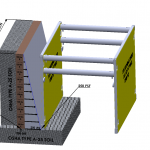
- The psf rating is derived through structural calculations of the shoring equipment. It represents a safe allowable load derived in accordance with nationally recognized design standards. Depending on the manufacturer and engineering calculations that number will typically include some sort of safety factor and might be roughly 65% of the failure load. A 900 psf rated shoring shield would fail at roughly 1400 psf. Figure 4 shows how a triangular soil load is applied to a shoring shield, and Figure 5 shows a rectangular soil load applied to a shoring shield.
The reason I refer to the rectangular diagram as the OSHA diagram is that they require that the box be rated for the deepest part of the excavation regardless of where the box is situated. There is another way to look at it if triangular loading is an accurate prediction of the load the box will see, then the full load the box would see is psf at the bottom times the box height divided by 2 totaling 250 psf x 10ft /2=1250 lbs. A rectangular diagram would give 2,500 lbs, twice as much. In actuality, the load is somewhere between the two numbers and the rectangular diagram provides an extra factor of safety.
From an engineering perspective the 25, 45, and 80 times depth numbers are fairly conservative but do have some disadvantages:
- Cohesive soil strength ranges from 15H (with H signifying the excavation depth) to as high as 100H. The 80H to 100H soils are marine clays. These soils can easily be sloped at 2:1 or greater. There is the potential for a dangerous safety gap here in the OSHA standard as the common assumption is that all soils transmit a maximum 80H lateral load and safe slope at no more than 1-1/2 to 1. Identification of marine clays is difficult and
 most likely out of the realm of the Competent Person. Marine clays are originated from coastal regions that have usually been settled out in saltwater. They can occur in inland regions today because of changing geology over geological time. The salt ions have an opposing attraction to the clay ions. This phenomenon causes the clays to settle looser and rearrange more easily.
 - Non-cohesive soil strength ranges from 15H to 60H. When engineers and safety managers decide to be precautionary and classify all soils as Type C they are putting themselves at a disadvantage. The 80H loading calculations after about 16 ft deep out of the normal range of shoring shields a 1-1/2 to 1 slope causes excessive sloping and benching limits and will preclude open-cut excavations.
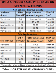
- These classifications are incremental causing a jump from one to the other, A-20,30,35, and 40 and C-60 are not available to the Competent Person, thereby eliminating the cost-saving advantages that go with them such as steeper sloping, more shore spacing for hydraulic shores, and use of lower-rated shoring shields or higher rated shoring shields deeper. Table 1 shows where 35 and 60 applies.
The way to eliminate these potential problems and gain a safer, cost-effective shoring system is to go to a site-specific engineered shoring system. In most applications, site-specific engineered plans really do pay for themselves. On engineered plans, we make it a point to use engineering calculations and not soil-type designations for this reason. All of the risks and costs listed above are eliminated.
PSF Rating As It Relates To Shoring Equipment
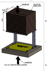
PSF means pounds per square foot. A 10 ft deep by 12 ft long shoring shield has 120 square feet of surface area. A shield rated for 1200 psf would be able to safely hold 1200 psf x 120 square feet = 144,000 lbs, see Figure 6.
For the competent person the only thing he has to be certain of is that:
- The soil load plus the surcharge load must be less than the shoring equipment rating.
Soil PSF + Surcharge PSF < Shield Rating
C-60 Soil
Manufacturers of shoring equipment have promoted and used in their tabulated data an intermediate Type C-60 soil classification that in the hierarchy falls between Type B and Type C soils. This category is generally accepted within the shoring industry by contractors and those reviewing worker protection plans. Federal OSHA and State OSHA programs do not appear to be opposed to this, however, Appendix A and the excavation safety standards do not recognize or address the Type C-60 soil classification.
In a January 10, 1994 response letter to a contractor’s question about C-60 soil OSHA recognized the fact that manufacturers could tabulate for C-60 soil but they reminded the contractor that they must test for the worst-case soil, which is considered by them to be C-80 soil.
Prior to the establishment of Appendix A in 1989 the original OSHA soil identification system also attached a soil lateral loading factor to the soil designations. They were often referred to as OSHA Type A-20*, Type B-40, and Type C-80 soils and indicated that for instance an excavation 20 ft deep in Type B soil would deliver a 20 ft x 40 psf = 800 psf lateral load to the shoring. For shoring equipment such as shoring shields at 20 ft deep in C-80, the shield needed to be rated 20 x 80 = 1600 psf, twice as much as for Type B soil and generally out of the range of normal shield construction at the time. In the case of trench jacks, some argued that cohesive C soil was too soft to stand long enough to get trench jacks installed and that the soil would slough in between even if one could get them installed. In non-cohesive C soil, they argued that excavation walls would not stand up long enough to get the shores in. Consequently, tabulated data developed by OSHA for hydraulic aluminum trench jacks only addressed soil Types A and B.
In response to the fact that there is plenty of soil that does not meet the Type B soil requirements that stands up and acts more like B than C soil, the shoring manufacturers defined Type C-60 soil and developed tabulated data for use of their equipment under this category. The very simple and easy way to use defining test for C-60 soil is the following;
Manufacturers Definitive Test for Type C-60 Soil-If the soil stands up long enough to install the shoring it can be considered C-60.
In the design and tabulation of operating data of shoring equipment in C-60 soil, a 60 times excavation depth rectangular load is anticipated on the shoring.
*When the OSHA standard was adopted in 1989 they dropped the 20, 40, and 80 tag intentionally because they did not want anyone relying on it.
Requirement for use of OSHA Appendix A-Soils
OSHA Appendix A is the soil classification process that must be used when using the other appendices in Subpart P. Most manufacturers make it a requirement for use of their tabulated data; however, there is no OSHA requirement that it be used. As long as the tabulated data provides a method for identifying the soil they can use or define any identification system they want as long as it is clear and the intended user understands and can apply it.
When assessing whether C-60 soil can be considered a worst-case scenario, please be advised that OSHA does not regard the C-60 classification as including the “worst” type of soil. If therefore, a manufacturer’s tabulated data covers soil only through the C-60 classification, then the data does not cover all possible soil types. An employer who elects, for convenience’s sake to treat the soil, in an excavation as C-60 would still have a duty to ascertain that the soil is not in fact worse than C-60.
DISCLAIMER: the information contained in this article is provided for general and illustrative purposes only and is not to be considered Site Specific and or designated engineering for any project or work zone, nor is it to be used or considered to be tabulated data, technical data, advice and or counsel to be used on any job site. Each project is different and is the responsibility of the employer’s designated Competent Person to make decisions on what systems and methods may be used in compliance with the federal and local regulations, manufactures tabulated data, engineered drawings, and other plans.
