


Site Specific Engineered Trench Shield Application Proves Effective for Contractor
Due to increased traffic congestion around a large airport, a Midwestern municipality had initiated a project to create a new toll road into the airport to ease traffic congestion. The project would require the contractor to update and or relocate surrounding utilities and infrastructure lines. On this particular phase of the project, the contractor would be relocating electric lines and then pouring concrete over the Pvc pipe containing the electric lines. The project would require a linear run of up to 200-ft with widths varying from 4-ft to 8-ft and depths from 8-ft to 16-ft. The contractor’s Competent Person had classified the soil as a Type B soil for the first 12-ft of excavation depth and as C-60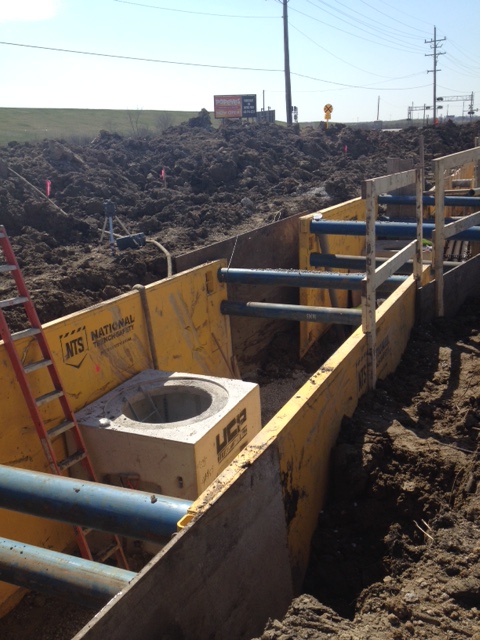 below 12-ft. The contractor would be performing the work along a busy local road consisting of four lanes of traffic and which would need to be open cut to run the lines at three points. The contractor had estimated that with the workforce assigned to the project, approximately 200-ft of pipe could be laid per day. The contractor was also looking for efficiencies with the excavation requirements and need for forms where possible.
The contractor called NTS to discuss shoring options for the project. After a thorough review of potential shoring options, the contractor elected to use steel trench shields along with steel rock boxes for soil and sediment containment. The contractor elected to use site-specific engineering to modify the capability of the trench shields further. The engineering allowed for steel road plates to be placed between the trench shields at set intervals and with an engineer’s approved overlap of the shields to limit the number of shields that needed to be set as the project progressed. The steel trench shields provided an efficient means of protecting the workers and the availability to change spreader lengths for lateral support and to stack additional shields for vertical support provided a solution for the changing depths. The contractor was also able to use the shields as a brace for forming the concrete by spacing timber forms against the trench shield walls. As the excavation progressed, the contractor could remove the trench shields as they work in a particular area and move those to the newly excavated area at the other end.
The contractor was very impressed with NTS’s capability to supply protective equipment the length of the project as well as the speed at which additional protection was provided to stabilize a section of the trench when they encountered water at a depth of 14-ft.